
Shaft alignment
Shaft alignment is a crucial process in maintaining the balance and efficient operation of machinery.
Proper shaft alignment includes addressing issues such as soft foot,
using shim plates, and dealing with spacer shafts.

MAGNET MOUNTING BASE
It is a device that can quickly and conveniently attach objects
or other equipment to metal surfaces without the
Sale!


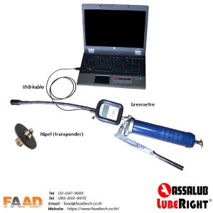

Lubrication Tools, On-site oil analysis, Online monitoring